Department of Electrical and Computer Engineering

ECED 4260 IC Design and Fabrication

Lab1 Fundamentals of Digital Design

OBJECTIVES 

 To get familiar with RTL Implementation, Structural and Behavioral coding of VHDL. At the register-transfer (RT) level, the basic building blocks are modules constructed from simple gates. They include functional units, such as adders and comparators, storage components, such as registers, and data routing components, such as multiplexers.  

Part I : Implementation of a 2-to-1 Multiplexer 

A 2 to 1 multiplexer has two inputs (a) and (b) as well as a select signal (sel).  The truth tables for the operation of a multiplexer is given:


ab
sel
00
01
11
10
0
0
0
1
1
1
 0
1
1
0
  1. Prelab: Use this MUX_2 to start and draw the schematic of MUX_2 
  2. Compile this version of the MUX_2. Write a testbench to test it and save a copy of annotated waveform.

Part II : Structural Implementation

For this part of the lab, you will structurally build and test a 4-input MUX using the RTL description of a 2-input MUX  as a base component. Use this MUX_4 to start and save it as "MUX_4.vhd".

Part III : Behavioral Implementation

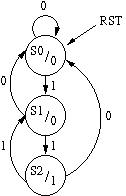
Build and test a design for a three state Moore machine.  The Moore machine is built to detect an non overlapping pattern of "11" with an asynchronous reset.  State machines are built using behavioral VHDL.   The state diagram for the pattern detector is provided.


Part of the VHDL code is given for the pattern detector ( There are couple errors, you have to fix them to pass the compilation) :

entity PatternDetector  is
        port(
                clk, reset, x : in std_logic;
                y           : out std_logic
            );
end  PatternDetector;

architecture behavioral of PatternDetector is

        -- Declare a new type for the states and declare
        -- three states
        type state_types is (S0, S1, S2);
        signal state: state_types;

begin

        -- Create a process that handles the state transition
        process (clk, reset)
        begin
                if (reset = '1') then
                        state <= S0;
                elseif (clk'event and clk = '1') then
                        case state is
                                when S0 =>
                                        if (x='1') then
                                                state <= S1;
                                        end if;

                                when S1 =>
                                        if (x='1') then
                                                state <= S2;
                                        elsif (x='0') then
                                                state <= S0;
                                        end if;

                                when S2 =>
                                        if x='1' then
                                                state <= S1;
                                        elsif x='0' then
                                                state <= S0;
                                        end if;
                        end case;
                end if;
        end process;

        -- Define the outputs based on what state the machine is in.
        with state select
                y       <=      '0'     when    S0,
                                '0'     when    S1,
                                '1'     when    S2;

end behavioral;


Lab submissions:


Last Updated: September 19, 2023